GEORADAR GSSI
The ROADSCAN 2 Mobile Radar System is a device designed to test the thickness and type of structural layers of road pavements and subsoil, and to assess the condition of reinforcement and concrete in bridge deck slabs. The modular design of the system as well as the control software “open” in terms of configuration increase the measurement range of the device. The technological solutions used in this device also make it possible to perform more advanced measurements of parameters such as the moisture content of pavement structures, the level of the ground water table, the depth of frost, the location of voids in concrete pavements, the location of cables or the state of corrosion of reinforcement.

The device consists of the following components:
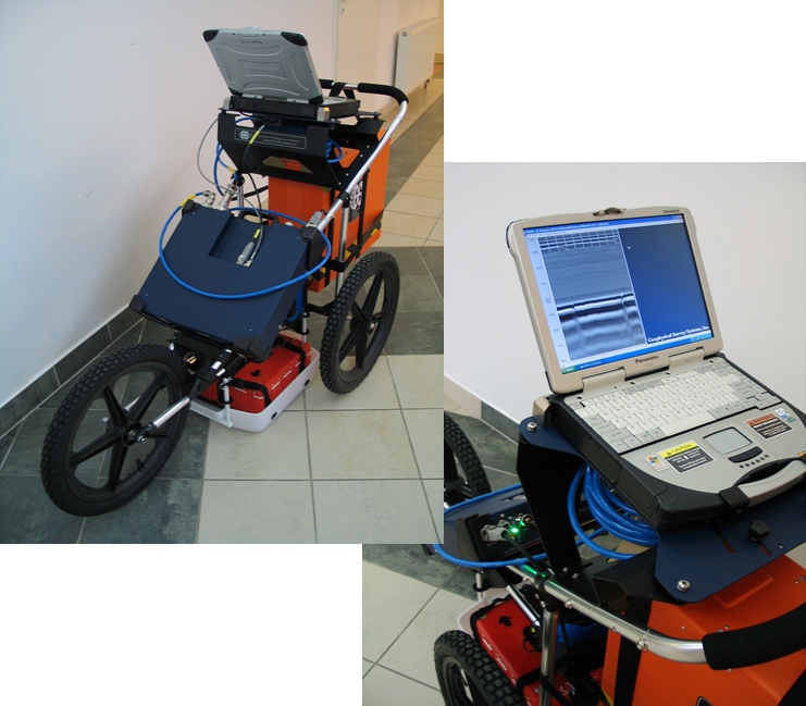
- power, control, recording and data processing unit:
SIR-20 central processing unit with Panasonic computer
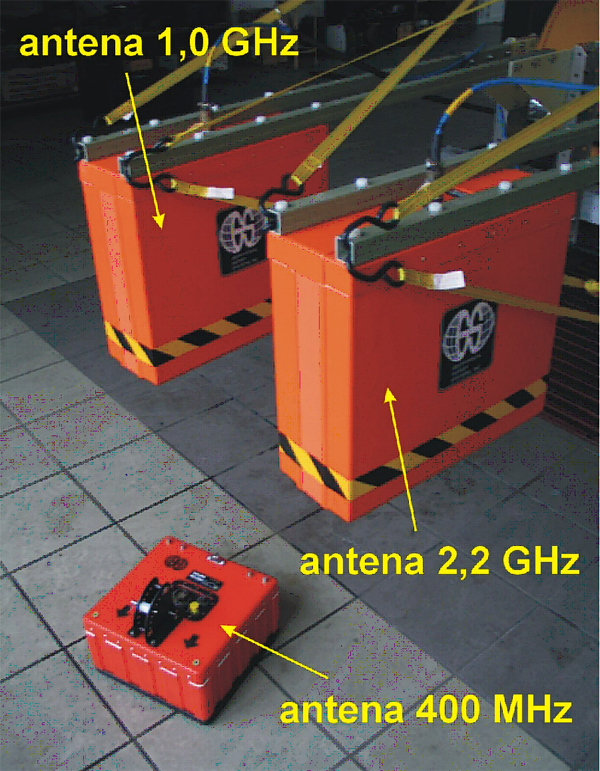
- GSSI antennas with frequencies:
- 2 GHz (penetration depth of about 300 mm, minimum thickness of the measured layer 20 – 30 mm),
- 0 GHz (penetration depth of about 700 mm, minimum thickness of the measured layer 70 – 80 mm),
- 400 GHz (penetration depth of about 3000 mm, minimum thickness of the measured layer 200 mm)
- 260 MHz (penetration depth of about 5000 mm, minimum thickness of the measured layer 600 mm)
- distance measurement sensor.

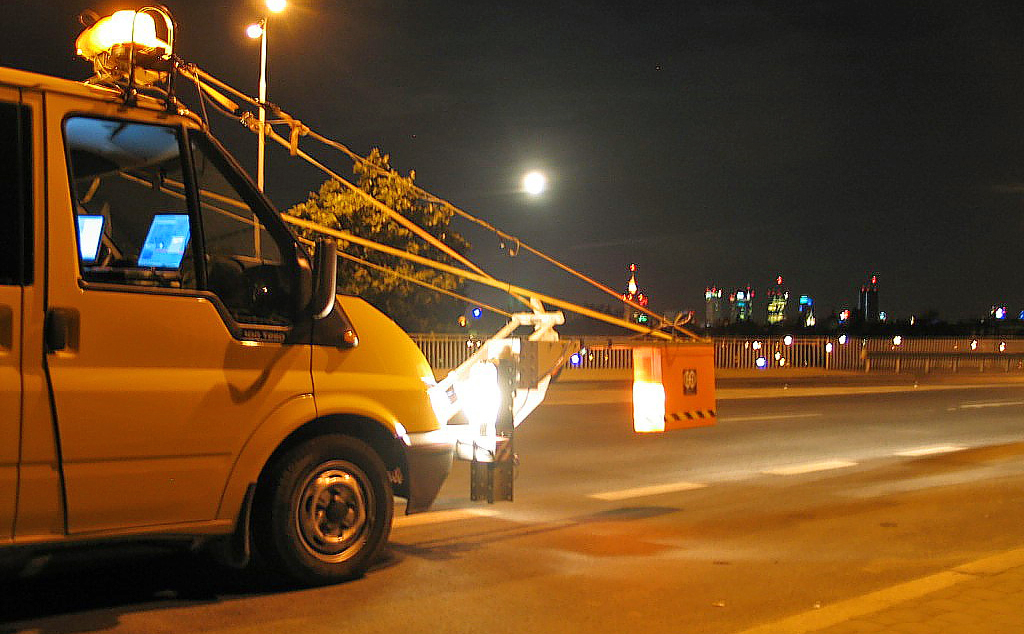
The aforementioned elements are installed on a specially prepared measurement vehicle, so that measurements with all antennas as well as selected antenna sets can be carried out on the move.
A measuring truck, which is used for geotechnical measurements, especially in areas that are difficult to access by a survey truck, is an additional piece of equipment.

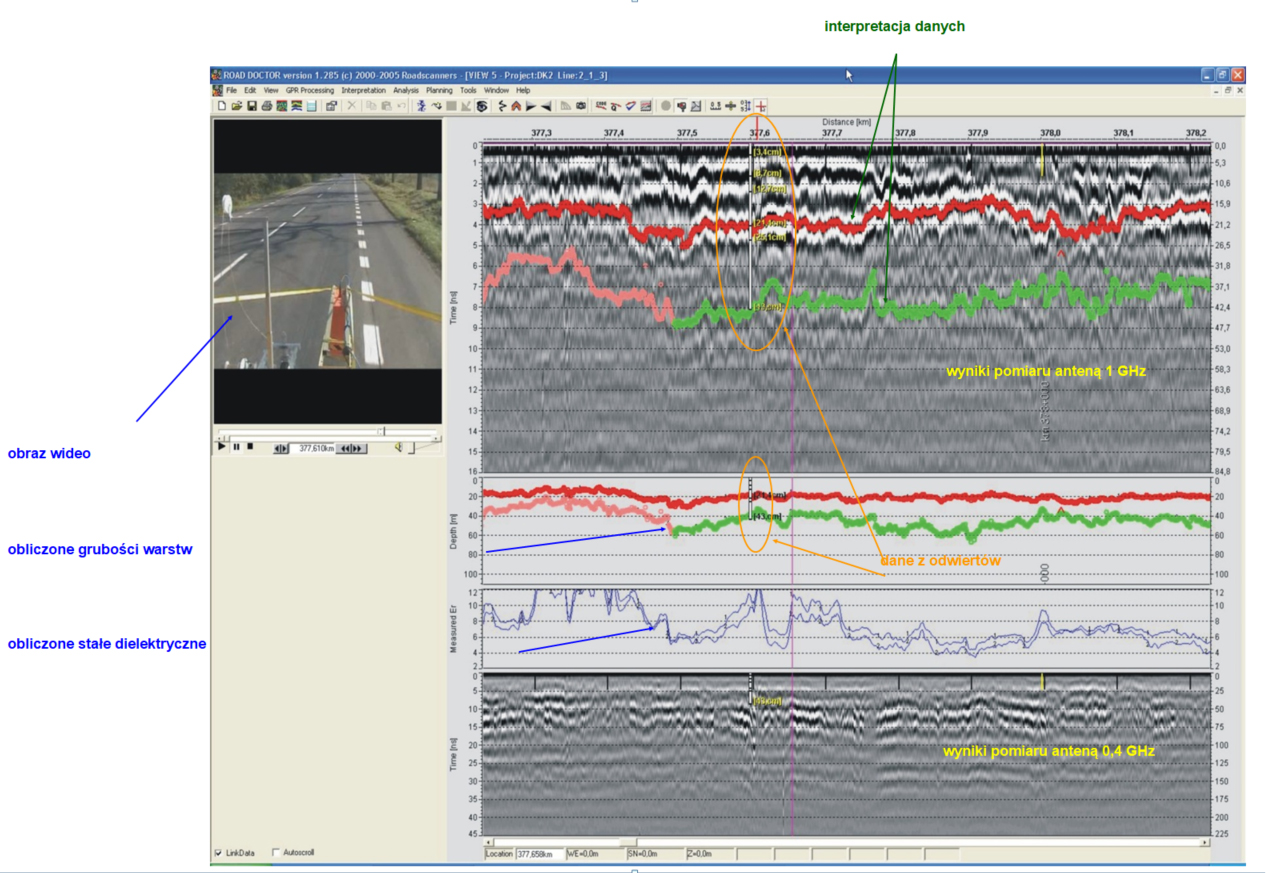
High-end software to support the data interpretation process is an essential part of the measurement system. RADAN, Road Doctor 3D and GPRSLICE, among other programmes, are used for data visualization and processing. Depending on the purpose of the measurements being conducted, the operator can choose this software to enhance the efficiency of the interpretation process. Below is an example of the user interface in Road Doctor 3D.

The advantages of GPR are used by many agencies involved in managing road networks. Some of the most common applications of radar technology include layer thickness measurement, void assessment, locating objects in the ground, and more complex ones used as supplementary tests such as assessing delamination, cracks, evaluating binder loss or leaching near bridge and overpass abutments. The basic measurement capabilities of the radar systems are shown in the table.
Table 1 Selected design features that can be measured with sufficient accuracy by using different types of radar
|
features selected |
measuring speed |
radar characteristics |
|||
|
low <20 km/h |
high >50 km/h |
400-500 MHz gp* |
1 GHz h* |
2,0 – 2,5 GHz h* |
|
|
redesign |
yes |
yes |
yes |
only to a depth of about 600 mm |
only to a depth of about 400 mm |
|
minimum thickness of the measured layer |
yes |
yes |
100 mm (200 mm for the top layer) |
50 mm for all layers |
25 mm for all layers |
|
voids under unreinforced concrete slabs |
yes |
yes ** |
only if the depth of the void is significant |
yes without the possibility of quantitative evaluation |
not found |
|
moisture content of the auxiliary subbase |
yes |
yes |
yes |
not found |
penetration depth too shallow |
*) the gp-type (ground coupled) antenna is placed directly on the surface of the structure under test, while the h-type (horn) antenna is placed about 45-50 cm above the structure under test,
**) if the void size greater than the measurement frequency
 EN
EN  PL
PL  DE
DE  FR
FR  IT
IT  ES
ES  CS
CS  SV-SE
SV-SE  DA
DA  NL
NL  HU
HU  RO
RO  UA
UA 


